Straight to the Point
After spending a few weekends designing custom wheels, then more weekends finding a way to attach them to a chassis so they’re in full view, I design a chassis which hides the wheels. Not quite.
My idea has always been to create more unique designs than what are commercially available. While I would like to use my custom wheels and keep them in full view, I’m not going to let that restrict my designs.
Especially when most people would prefer boring metal wheels. Not that I care about other people, but I might put these designs up for download one day.
The Idea
I wanted to design a chassis which has a standard axle end connector, while keeping as much of the wheel visible as possible.
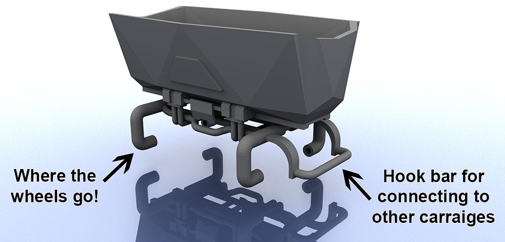
My pipe chassis from the previous article was slightly modified to be a simple hauler. Though a little more modernised. It’s nowhere near a final look and I may never even use it. The design is simply to test scaling against other rolling stock, to make sure axles spin freely with my design and that existing carriages can connect with my coupling system.
I also need to design one of those hook connectors. One day.
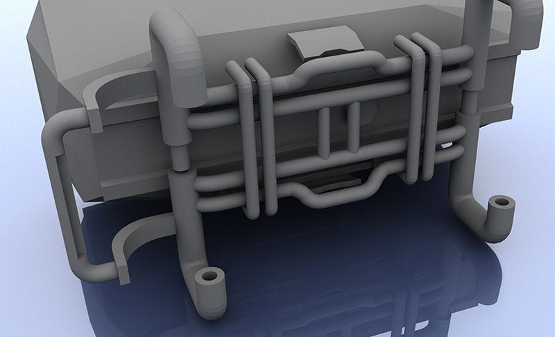
This chassis connects to the the outer edges of the axles via hollowed pipes. Very similar to how regular commercial carriages work, only mine doesn’t have the real world detailing; suspension, brakes and such. This means more of the wheel is visible.
Compared to my clamps, friction should be a lot less. Though my concerns about that have mostly been alleviated.
This chassis is less likely to snap if axles are regularly being swapped. I think. Only one way to find out.
How Did it Come Out
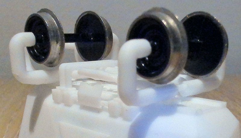
Quite well. The scaling is almost there and the wheels roll. Always a bonus on trains! It was intended to be a tall design so don’t read too much in to that. For a final print I would dip the absolute center of the model down to fill the void between wheels.
My design looks weird being so tall. It can be lowered easily enough. Or more detailing added to the underside to make it look fuller? I’ve got some crazy ideas.
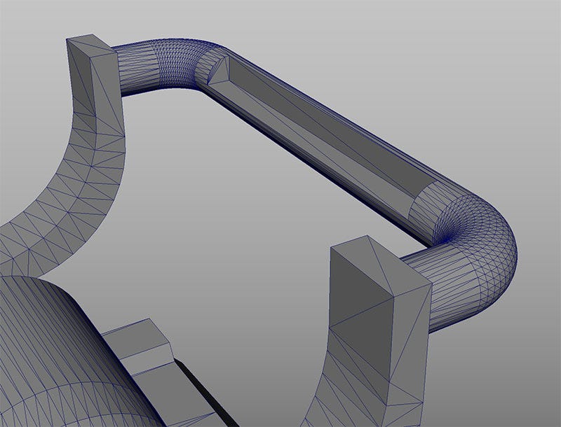
There’s a big issue with the above screenshot which I would hope people have noticed! The coupling… thing, is too high. I carved out a section of the bar so hooks would grab easier. Works perfectly. Just a bit too high.
Pipes connecting to the axles are a tiny bit too wide. That was by design, but I’m not really liking it. I can reduce the width, slim the pipes or swap them out for something completely different. All I need are reliable measurements for my axle lengths and I can build anything.
Speaking of which. My axle length measurements were a bit off. I’m blaming the cheapest electronic calipers I could find on eBay. Or Maya. It has some quirks with exact measurements. Basically, it’s everyone fault but my own.
My wheel measurements were off by around 0.5 mm. Doesn’t sound much but it’s enough to bow the connecting axle pipes and prevent the wheels from spinning.
All I did was file a little plastic off either side and the wheels gained a decent amount of play. I tried metal axles first and they spun almost as well as production models. The difference is so minor that I’m not going to waste time improving them.
My plastic wheels also saw little friction difference in comparison to my clamp design. They may even spin a but better. Obviously still not as wheel as metal variants.
The wheels slot in to a hole which was formed by intersecting a cylinder. I think resistance could be lowered if I made the end of this cylinder spherical? I’m wary of tolerances with my 2k printer and feel it would be a waste of time even trying.
I’ve performed 10+ axle swaps without issue. Everything flexes and returns to its original shape. With clamps I’m always worried they’ll snap and render the print useless. The fix is to stop swapping axles so much!
I’m very happy with the durability and functionality of this design. Not sure if I would use it over clamps. I guess it would depend on what the rest of the model looked like.
Size Doesn’t Matter… Until it Does
Earlier, in my initial wheel design posts, I mentioned that the various metallic wheel sets I had varied in size. Ever so slightly, though enough to confuse me when trying to design my own wheels.
The difference between them was around a diameter of 0.5 mm. I went with the higher value when designing the chassis and left very little space for error. I planned for a half millimeter gap.
Whether it was good measurements or luck, I’m not complaining.
Definitely something to factor in my other designs. I don’t want to raise the model body any higher, so I’ll change the way pipes connect. Ideas aplenty for that.
To Do
Almost done with the boring stuff. Once I’ve got the chassis perfected and reliably printing then I can begin building what’s in my head. Scary thought.
All this measuring and printing is for a purpose. There’s no point designing something unique if it won’t roll along a track or couple on to existing freight.
That’s the word I was thinking of 3 posts ago! Freight. Never claimed to be a good writer.
Improvements for the next build:
Lower the coupling bar by around 0.5 mm.
Increase the space between axle pipe connectors by around 1 mm.
Increase the depth of the cavity which the axles slide in to by… as much as possible without compromising the integrity of the superstructure. To test if the axles spin smoother.
I don’t want to shave too much off. If there’s a slight rubbing I can always file each print down. It takes seconds and doesn’t affect the look.
Design some hook systems so this chassis can hook on to other rolling stock.


